QUICK TIP: Timber in Tekla Structures - CLT walls
The Construsoft Timber bundle extends Tekla Structures with tools for timber modeling, detailing and fabrication. In this quick tip, we follow a CLT wall from modeling and elementation through lamella visualization and production drawings, all the way to a machine-ready BTL file.
Step by step modeling for timber fabrication
Modeling a CLT wall and assigning materials with presets from manufacturers
IMAGE: You select a CLT preset in the Wall Layout tool in Tekla. This is how you design a material with laminate properties according to the manufacturers specifications. Screenshot from the Timber in Tekla Quick Tip video above.
The example in our video starts with a wall layout containing two windows and a door.
Using presets included with the Construsoft Timber bundle, the wall can quickly be turned into a CLT wall based on catalog products from different Timber manufacturers.
Missing any CLT materials?
→ Reach out to Construsoft
The selected CLT preset also defines the individual lamella layers and their fiber orientation, with the information stored directly in the model object properties.
IMAGE: The CLT wall has been cut into sections for manufacturing and transport. The ridge laps are included automatically. Screenshot from the Timber in Tekla Quick Tip video above.
The ‘Wall layout elementation” tool help divide larger walls into elements according to dimensions and margins that you define.
In this example you can see how the CLT preset also ensures that ridge laps are automatically created at the required intervals with sufficient margins (which you define) to openings.
Are you a timber manufacturer/fabricator?
Do you want your materials available in Tekla Structures?
IMAGE: A CLT corner connection modeled with the Construsoft Timber package. Screenshot from the Timber in Tekla Quick Tip video above.
Corners and other CLT wall connections
The same approach can be used for more than individual wall elements. The Timber bundle also includes tools for creating typical CLT connections, including corners and T-connections between walls.
The video shows a few examples, but the tools demonstrated here are only part of the complete Construsoft Timber bundle.
Visualizing CLT lamella layers in the 3D model
IMAGE: The CLT Lamella Visualizer helps you verify what you have modeled. The colors indicate fiber direction as well as any coatings. Screenshot from the Timber in Tekla Quick Tip video above.
With the ‘CLT Lamella Visualizer’, the layer information can be displayed directly in the Tekla model.
The individual lamellas and their fiber directions become visible, while surface colors make it easier to distinguish the inside and outside faces of the element.
This provides a quick visual way to check that the CLT element has been defined correctly before moving further into detailing and production.
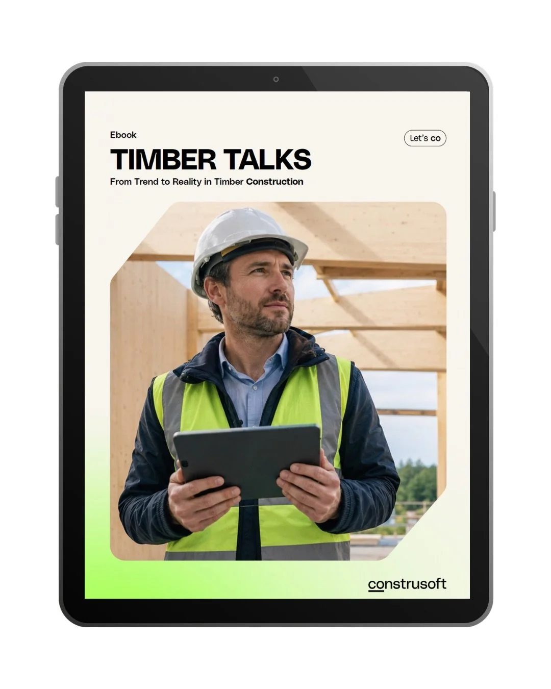
Ebook: Timber Talks — From Trend to Reality in Timber Construction
Learn about the trends, challenges, and workflows shaping modern timber building.
Use this practical guide to align your team, prepare client and partner conversations, and identify key questions before pursuing timber projects.
Creating CLT drawings
IMAGE: Drawing showing the CLT lamella details. Screenshot from the Timber in Tekla Quick Tip video above.
The Construsoft Timber bundle also includes predefined drawing configurations for different types of timber elements.
These provide a starting point for creating production and assembly drawings directly from the Tekla model, including the lamella information needed for CLT fabrication.
Exporting fabrication data from Tekla Structures
IMAGE: Export of BTL files that can be imported to fabrication machines directly from Tekla Structures. The green indicates that all the requirements have been met. Screenshot from the Timber in Tekla Quick Tip video above.
The model information can also be taken directly into fabrication. The Construsoft Timber bundle includes dedicated export extensions for a range of timber fabrication machines and file formats.
For beam and sheet processing, the BTL Export supports workflows for machines from manufacturers including Homag, Weinmann, H&M, SCM, MBA, Graule, Stromab, Biesse and Reichenbacher.
Dedicated export tools are also available for Hundegger BVX and BVN, Weinmann WUP, TigerStop, H&M and plate-cutting machines using Ardis.
BTL Export
In the video, we demonstrate the BTL workflow. Before export, the tool checks the model and provides a process log highlighting operations that do not match the required machine-operation naming conventions. The reported objects can be located directly in the model, making it easier to identify and correct issues before production.
Operation names can then be corrected or mapped using aliases in the export settings. Help documentation is also available directly from the component dialog to assist with the required naming.
Once the process log is clear, the BTL file can be exported directly from Tekla Structures.
The resulting file can then be opened in a BTL viewer to verify that the geometry and fabrication operations have been transferred correctly before sending the data to the machine.
Note: It is of course important to make sure that responsibilities are clearly defined in terms of file export, control and verification before machining.
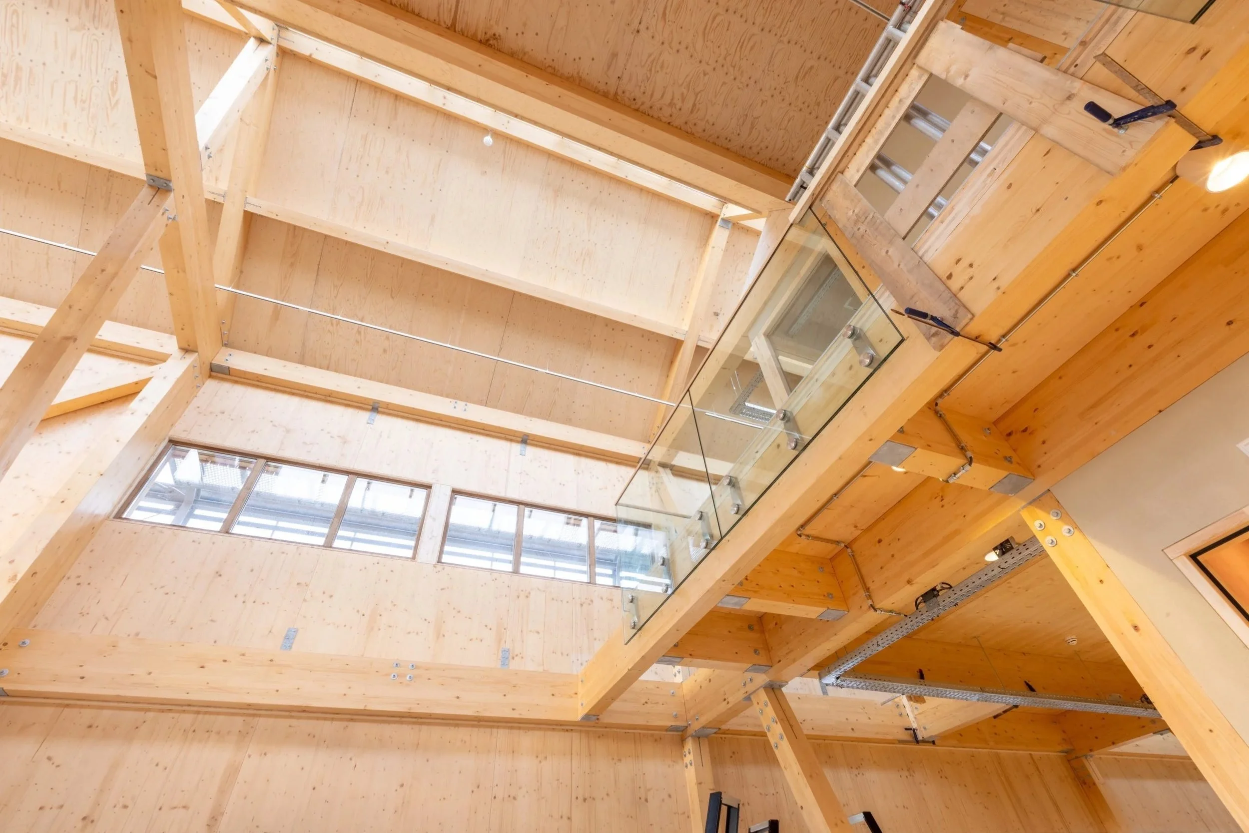
What is CLT?
BLOG ARTICLE: A practical introduction to CLT for construction and engineering professionals, explaining what it is, where it is used, and why coordination matters.
Read the article on our Construsoft global website:
Timber in Tekla is more than CLT
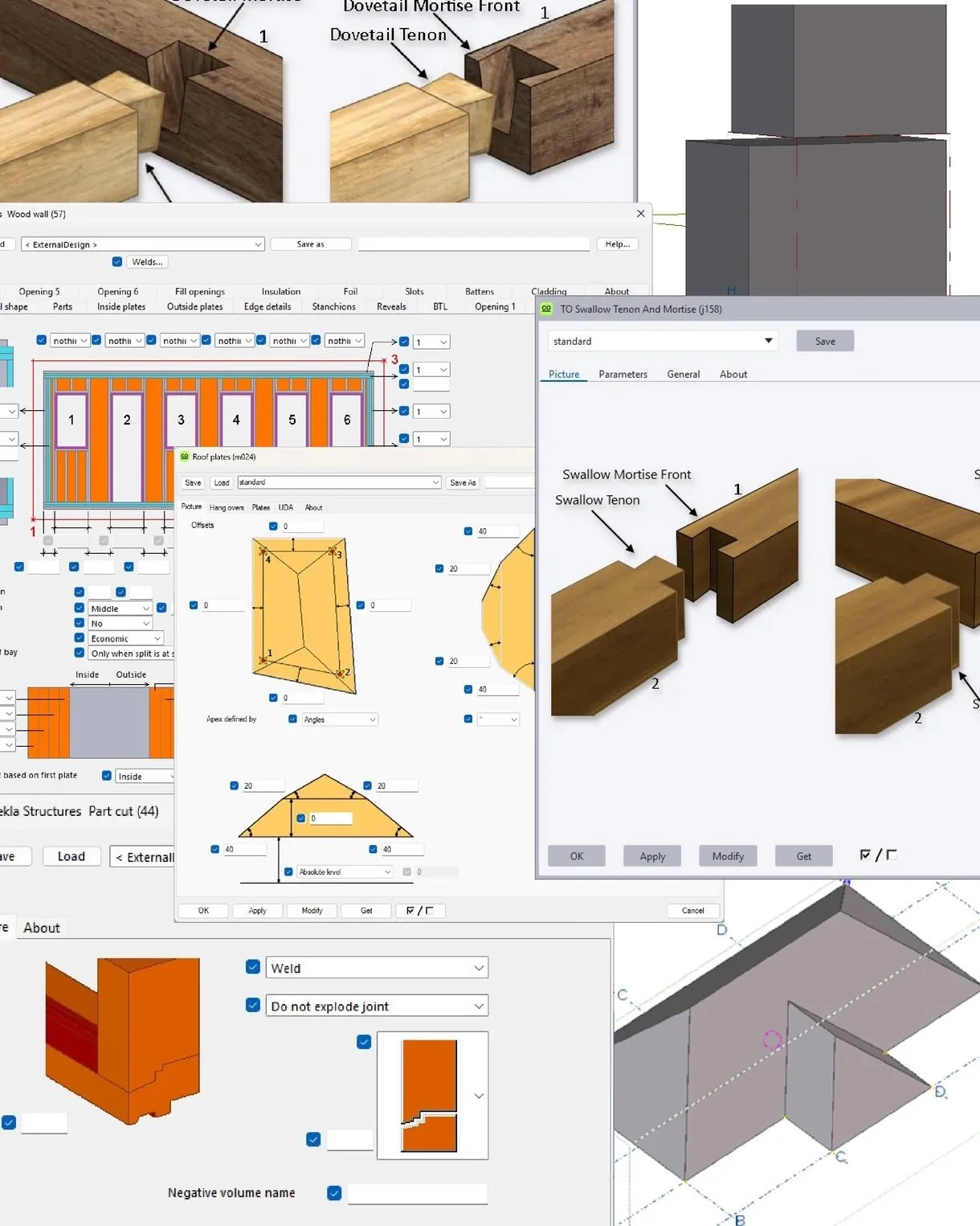
The Construsoft Timber package (buy online here) is designed to extend Tekla Structures for a broader range of timber structures and workflows.
In addition to CLT, it includes tools for efficiently modeling timberframe walls, floors and roofs, as well as a range of plugins for traditional timber structures. The Timber International environment provides predefined drawing configurations for walls, floors, roof frame assemblies, CLT elements, beams and plates.
The package also includes reports, lists, Organizer categories and object browser settings to help make better use of the information contained in the timber model.
Together with the fabrication export tools, this makes it possible to use the Tekla model beyond structural modeling and detailing, connecting model information with drawings, reporting and timber production.
Interested?
Reach out to our Timber team in Norway:

IMAGE: Frode Vollan, Construsoft

IMAGE: Anders Sjøberg, Construsoft
OTHER ARTICLES