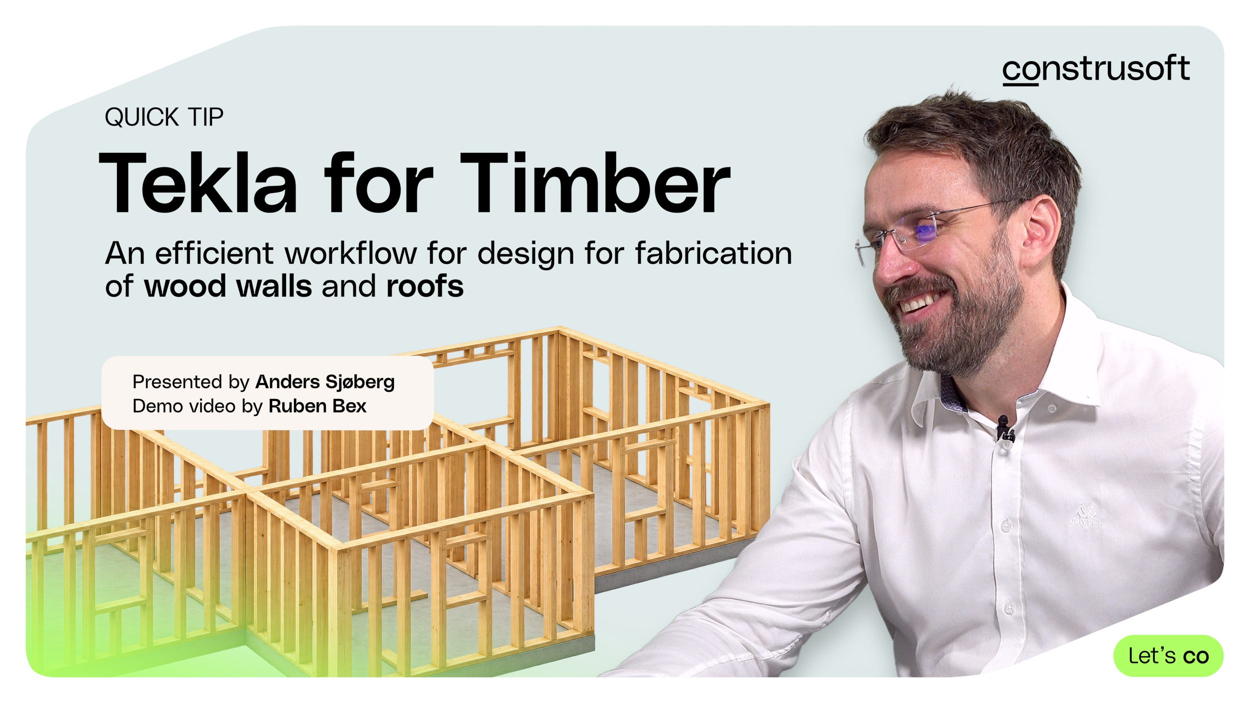
QUICK TIP: Timber frame modeling for fabrication with Tekla Structures
The Construsoft Timber bundle extends Tekla Structures with tools for modeling, detailing and fabrication of timber structures.
In this quick tip, we demonstrate how to create timber frame walls and floors using predefined configurations, manage changes to the design, and generate production drawings, reports and machine-ready fabrication data directly from the Tekla model.
Creating timber frame walls with the Wood Wall component
IMAGE: With the Wood Wall component we can define the different layers of the timber frame wall, including their materials and configuration. These settings can be saved as presets and reused across the project.
The workflow starts with the Wall Layout tool, where we define the wall elements, their dimensions and openings, much like modeling concrete or CLT walls.
With the Wood Wall component from the Construsoft Timber package, we can define the different layers of the timber frame wall, including their materials and configuration. These settings can be saved as presets and reused across the project.
The Wood Wall on Panel component then generates the complete timber frame structure inside the predefined wall elements, automatically adapting to their dimensions and openings.
Different presets can be applied to different wall types, such as interior and exterior walls. Multiple elements can also be selected and generated simultaneously, reducing repetitive modeling work.
Filter individual layers
Using model filters, we can hide individual layers to inspect the framing or other parts of the wall assembly.
IMAGE: Using model filters, we can hide individual layers to inspect the framing or other parts of the wall assembly. (Screenshot from the video above)
Managing changes to timber frame elements
One advantage of this workflow is that the original wall layout remains the guiding geometry for the timber structure.
If the design changes, we can modify the original layout, move walls, adjust dimensions or change openings.
The timber framing follows these changes, avoiding the need to remodel individual members manually.
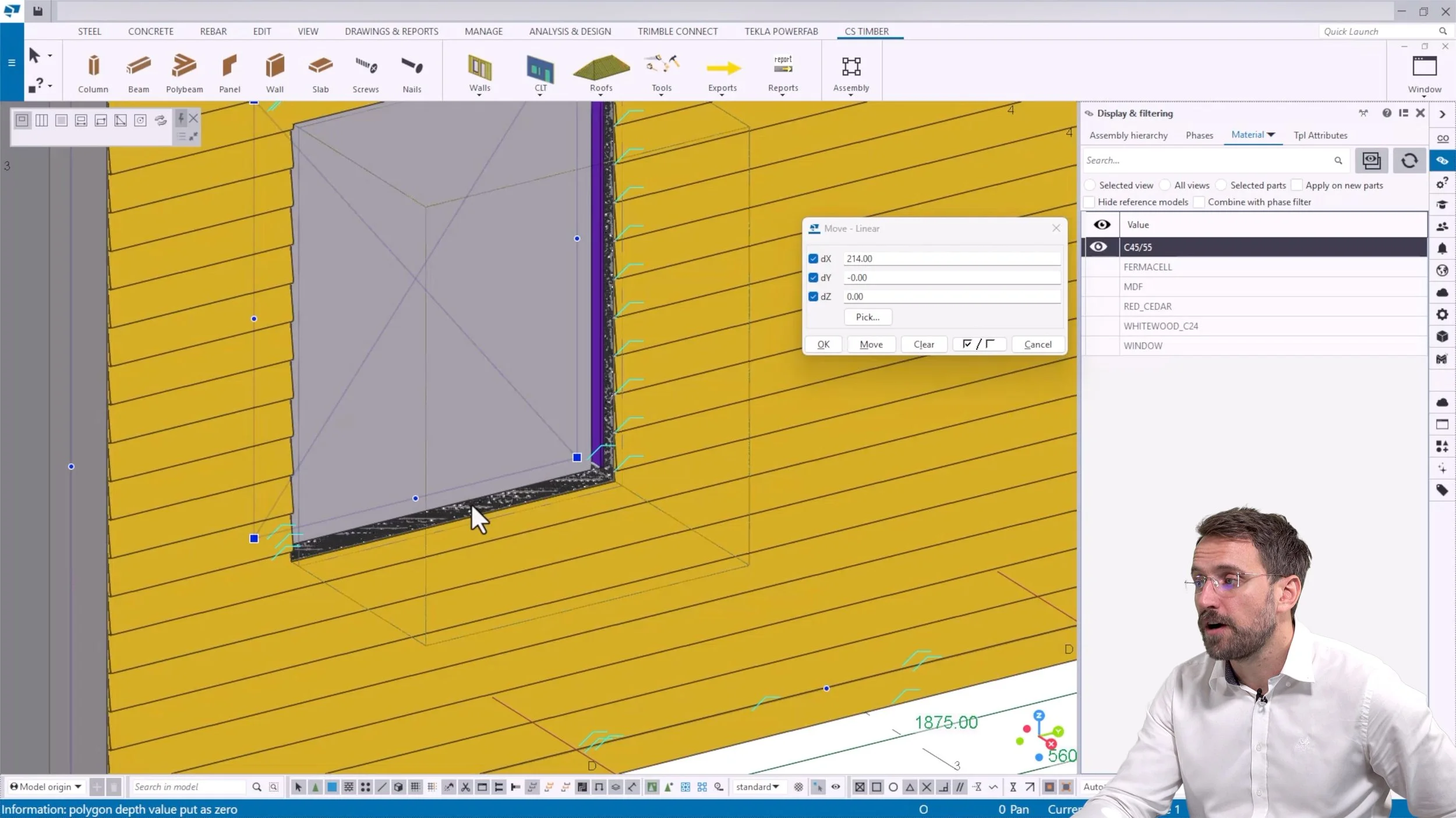

IMAGES: If the design changes, we can modify the original layout and the timber framing follows these changes automatically.
Modeling timber frame floors
IMAGE: The Wood Wall component can also be used to create timber frame floors and we demonstrate two approaches in the video: The floor structure can be placed directly by selecting three points, or we can use Tekla's Floor Layout tool to define the floor elements first.
The same Wood Wall component can also be used to create timber frame floors, simply by applying a different configuration.
There are two approaches demonstrated in the video. The floor structure can be placed directly by selecting three points, or we can use Tekla's Floor Layout tool to define the floor elements first.
With the second approach, Wood Wall on Panel generates the timber structure within the predefined floor elements, following the same workflow used for the walls.
Timber framing in multi-material projects
Many construction projects combine timber with steel and concrete. Since the Timber package works within Tekla Structures, timber elements can easily be modeled alongside other structural materials.
The video demonstrates this with a facade element adapted to fit around a balcony platform, illustrating how the Wood Wall component can also be used for configurations beyond standard wall and floor assemblies.

IMAGE: Since the Timber package works within Tekla Structures, timber elements can be modeled alongside other structural materials.
Production drawings and reports
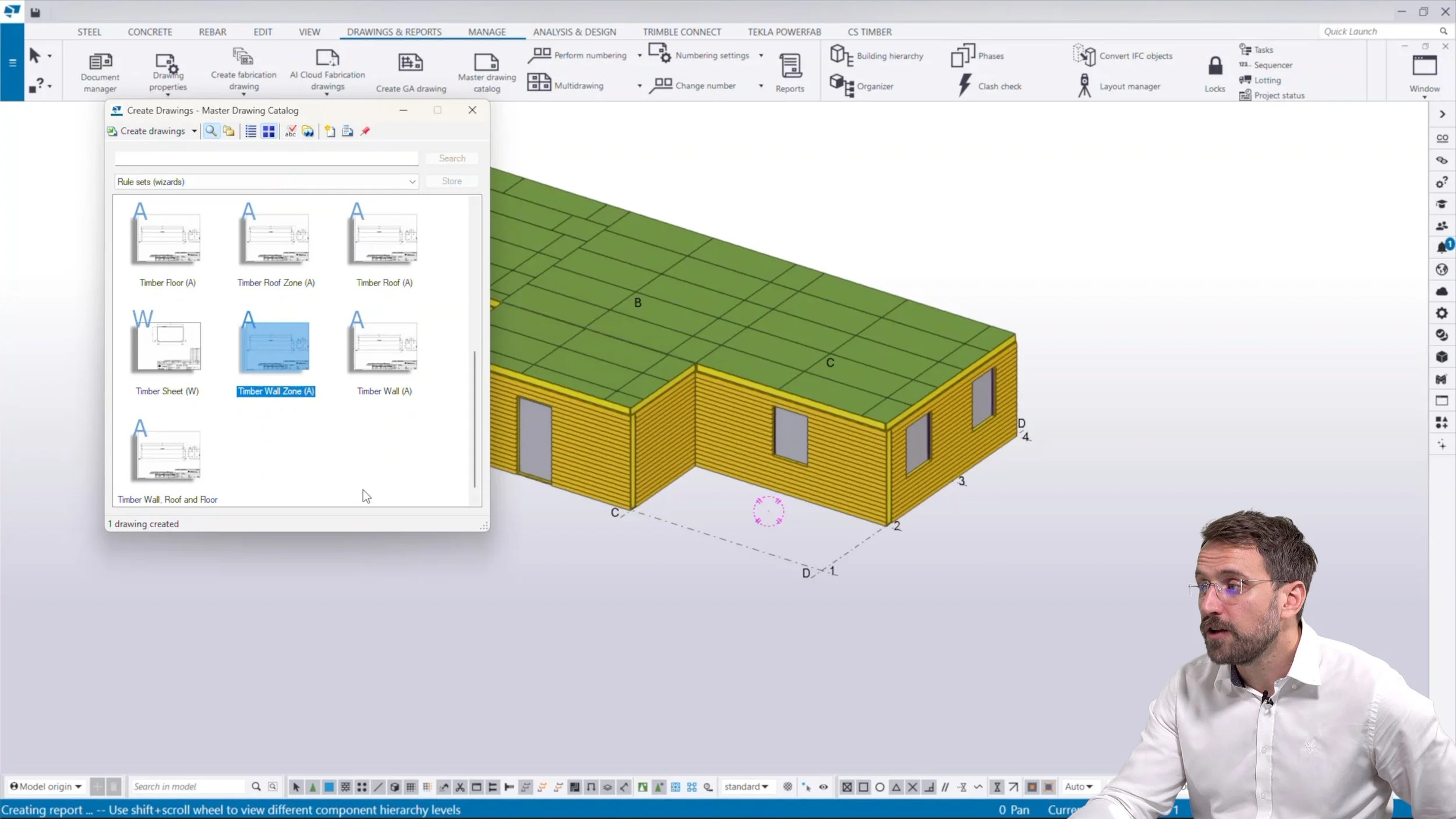
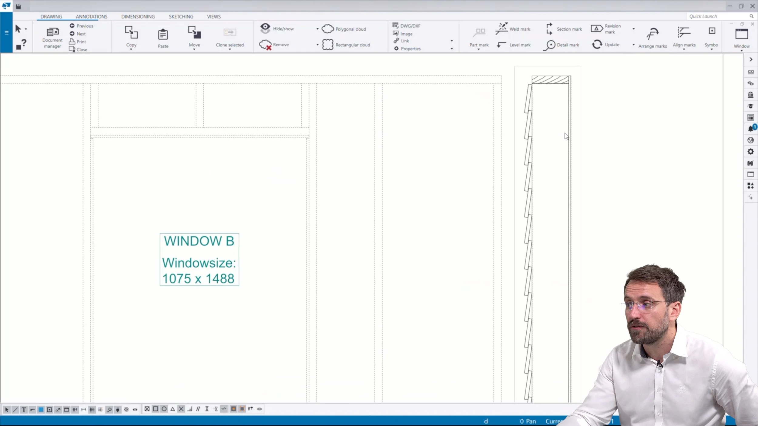
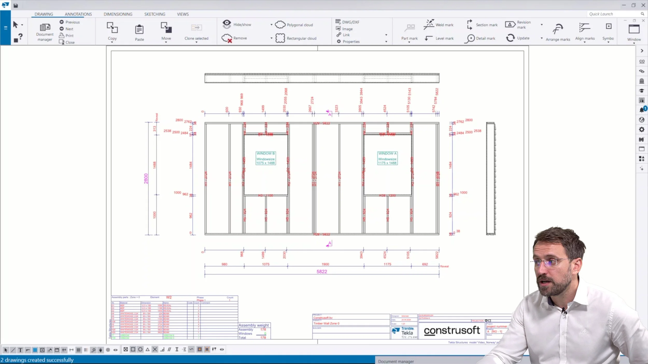
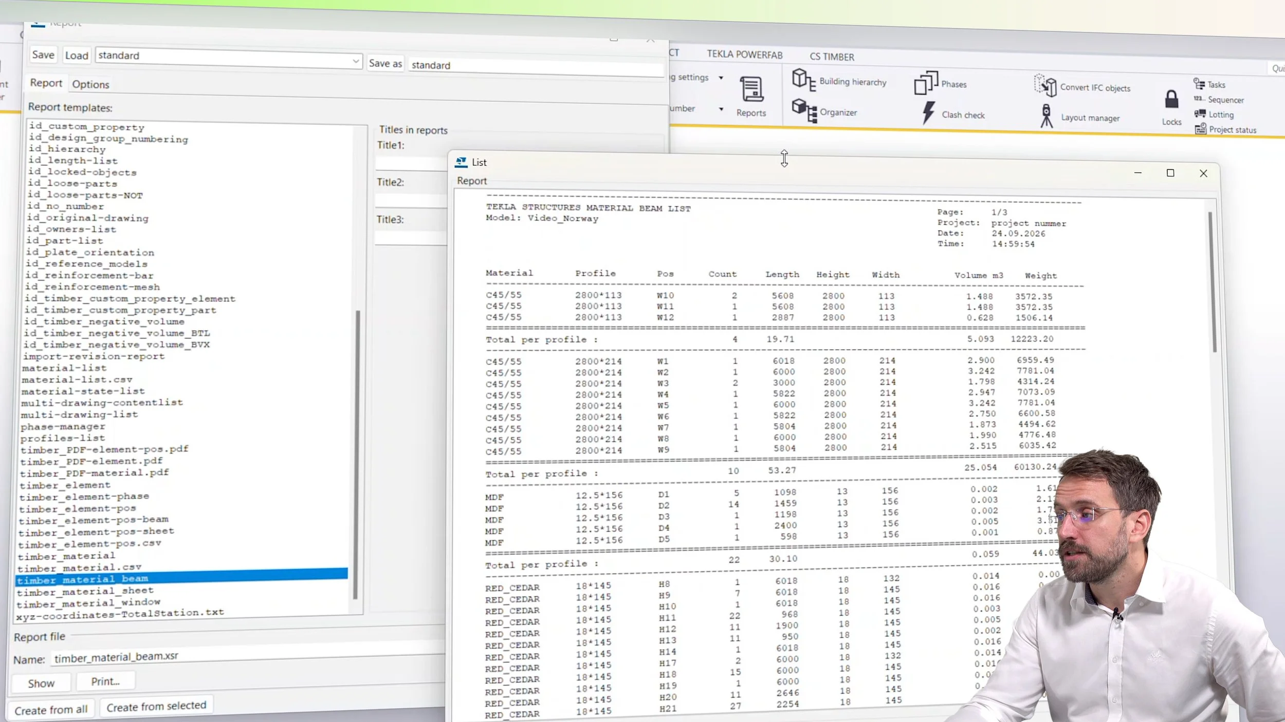
PICTURES: The Construsoft Timber bundle includes predefined drawing configurations for timber elements and assemblies, as well as predefined reports like saw lists, opening dimensions, wall element lists and timber percentages.
The Construsoft Timber bundle includes predefined drawing configurations for timber elements and assemblies.
Filters and drawing settings make it possible to control which layers of the timber structure are displayed, providing the information needed for production and assembly.
The package also includes predefined reports that extract information directly from the model, including saw lists, opening dimensions, wall element lists and timber percentages.
Exporting timber fabrication data from Tekla Structures

IMAGE: The Construsoft Timber bundle includes NC export tools for transferring model information to timber fabrication machines. This example shows a BTL file opened in the BTL Viewer.
Beyond drawings and reports, the Timber bundle includes NC export tools for transferring model information to timber fabrication machines.
Dedicated export extensions support formats such as Hundegger BVX and BVN, Weinmann WUP, TigerStop, H&M and Ardis. The BTL Export extension supports workflows for beam and sheet processing machines from manufacturers including Homag, Weinmann, SCM, Biesse and others.
BTL export
In the video, we show an example of a timber element opened in a BTL viewer, where the exported geometry and machining information can be inspected before production.
These export tools make it possible to transfer fabrication information directly from Tekla, reducing the need to recreate or process the same geometry in separate fabrication software.
Tekla BIM Awards
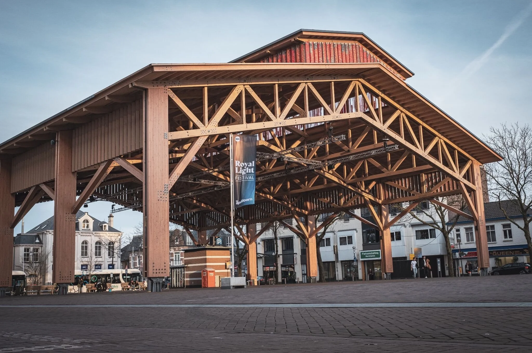
Apeldoorn is known as a warm, green city on the Veluwe. Until now, the market square was ‘unsociable’ and empty. This has been changed by the Apeldoorn Market Hall.
A wooden market hall that can be used for the market and for all kinds of other events, such as the fair or live performances.
Timber in Tekla is more than CLT
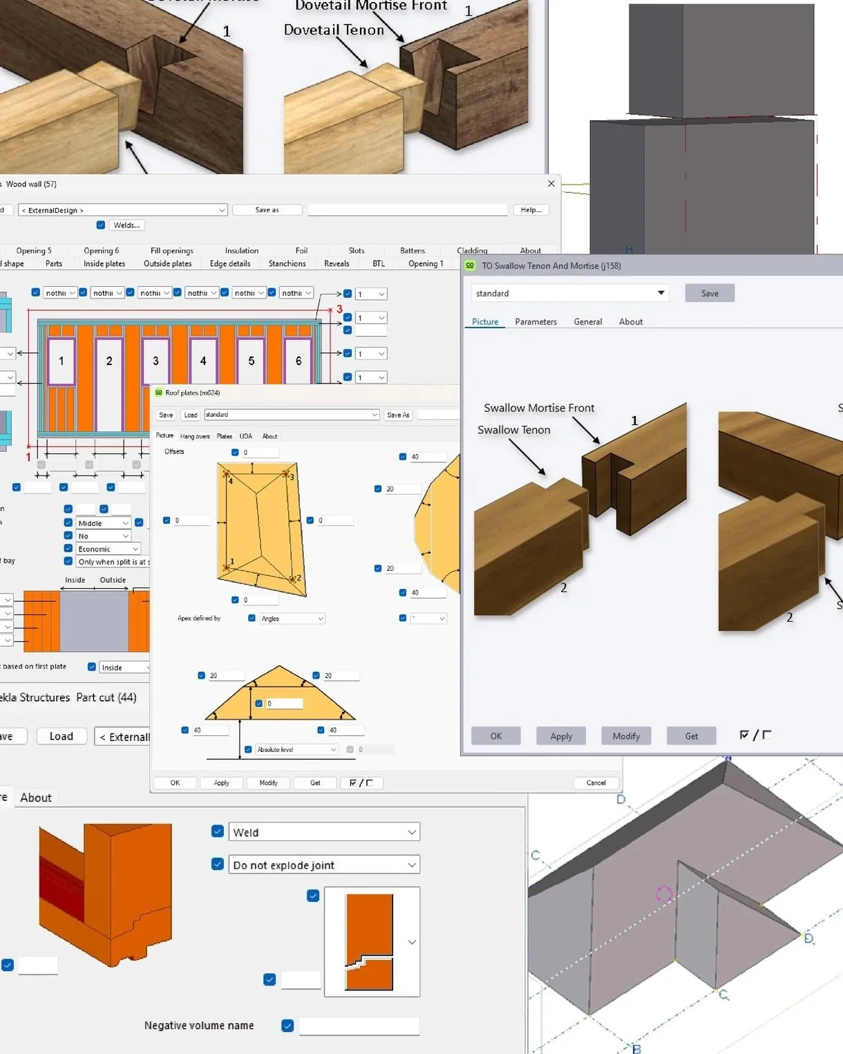
The Construsoft Timber package (buy online here) is designed to extend Tekla Structures for a broader range of timber structures and workflows.
In addition to wood framing which we covered in this article and quick tip video, it includes tools for efficiently modeling CLT, as well as a range of plugins for traditional timber structures. The Timber International environment provides predefined drawing configurations for walls, floors, roof frame assemblies, CLT elements, beams and plates.
The package also includes reports, lists, Organizer categories and object browser settings to help make better use of the information contained in the timber model.
Together with the fabrication export tools, this makes it possible to use the Tekla model beyond structural modeling and detailing, connecting model information with drawings, reporting and timber production.
Interested?
Reach out to our Timber team in Norway:

IMAGE: Frode Vollan, Construsoft

IMAGE: Anders Sjøberg, Construsoft
OTHER ARTICLES